1950-1/2 to 1956 Willys Utility Vehicles
Electrical diagnostics for instrument gauges
Some of this information comes from Willys service manuals and some from discussions on the WillysTech mailing list.
Questions or comments please E-mail me. Click here for contact information.
Diagnostic Information and Procedures
12 volt Conversion Information
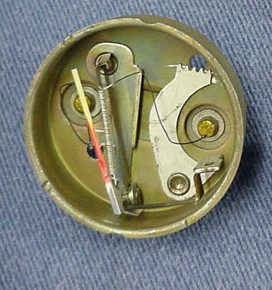
The Fuel, Oil and Temperature gauges are of the bi-metallic type construction. They are supplied with regulated power from the Instrument Voltage Regulator to improve accuracy. The fuel gauge is connected by a single wire to a float-and-slide-rheostat sending unit in the fuel tank. The temperature gauge is connected by a single wire to a sealed bulb unit mounted in the water jacket of the cylinder head. The oil pressure gauge is connected by a single wire to a diaphragm-type unit (75 ohm rheostat) mounted in an oil gallery of the engine block. The fuel, temperature and oil pressure gauges all appear to be the same mechanism with different faces. Each gauge has 2 terminals. The internal mechanism consists of a coil of "heater wire" wrapped around a bimetallic strip. Each terminal on the gauge is connected to one end of the heater wire and there is no connection to ground. The more current that flows through the heater wire, the more the bimetallic strip bends and the more the indicator needle moves to the right. Therefore the lower the resistance of the sending unit to ground, the more the gauge will deflect to the right. Due to their construction the gauges are not polarity sensitive and do not need to be grounded. Each gauge has two internal adjustments.
The Fuel, Oil and Temperature gauge sending units provide a variable resistance ground path for each gauge. The less the resistance of the sending unit, the more current flows through the gauge and the more the needle deflects to the right. This makes the sending units connection to ground very important.
The amp meter is a moving vane type meter and is different than the other 3 gauges. It is electro-magnetic and wired in a series circuit.
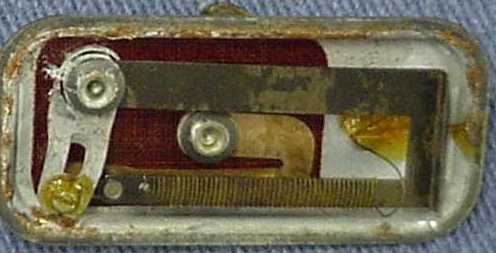
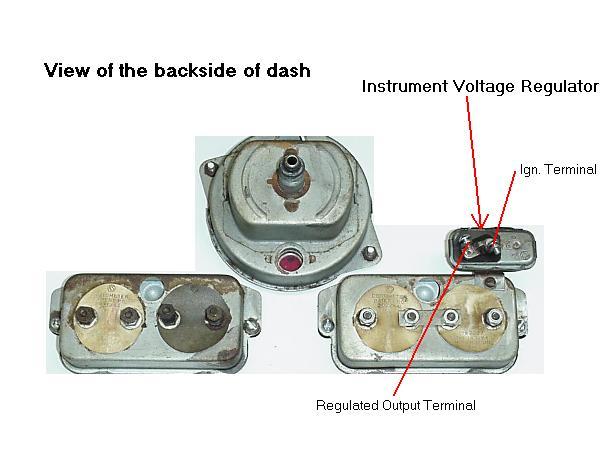
The Instrument Voltage Regulator maintains a constant amount of power to the gauges to improve their accuracy. This power is regulated by varying the duty cycle of the output, not by actually changing the voltage. The Instrument Voltage Regulator is mounted to the Fuel/Oil gauge housing, making the ground of this housing very important. Input voltage in excess of 8 volts will not affect gauge readings but will result in premature wear of the Instrument Voltage Regulator contacts. Input voltage of less than 5 volts will make the output too low and cause low gauge readings. The Instrument Voltage Regulator is a small rectangular box and it has two screw terminals. The case is ground. One terminal is labeled IGN, which is connected to ignition power. The other terminal is the regulated output terminal. It goes to each of the fuel, temperature and oil pressure gauges to supply them with regulated power. The internal mechanism of the Instrument Voltage Regulator consists of an on/off contact controlled by a coil of "heater wire" wrapped around a bimetallic strip. When the ignition switch is turned on power flows into the Instrument Voltage Regulator and through the closed contact then out to the 3 gauges. Power also goes through the heater wire to ground. As the heater gets hot, the bimetallic strip bends and opens the contact. With the contact open the power flow is interrupted to the gauges and the heater wire, so the bimetallic strip cools until the contact closes again. The on/off duty cycle determines the amount of power supplied to the gauges by the Instrument Voltage Regulator. There is an internal adjustment screw on the mechanism.
Diagnostic Information and Procedures
Keep in mind that even when operating properly the gauges are not extremely accurate. If a gauge reads too high, there is too much power flowing through it. If a gauge reads too low, there is not enough power flowing through it. The most likely problems are bad connections and miss-routed wiring. There may be more than one problem causing the symptom. Before replacing any part, check it against the specifications charts to be sure it is defective.
Suggested tools- Standard Automotive Test light, Digital
multimeter, Jumper wires.
Fuel, oil and temperature gauges ALL read too high or too low
If all three gauges read too high or too low, the Instrument Voltage
Regulator may not be functioning properly. Go to Testing
the Instrument Voltage Regulator
Only One Gauge Reads Incorrectly (except Amp Meter)
Testing the Instrument Voltage Regulator
Clean the connections at the Instrument Voltage Regulator and check
for correct wire connections using the wiring
diagrams. Check the voltage supply to the Instrument Voltage
Regulator ignition terminal. It should be battery voltage when the key
is on. Connect a jumper wire between the Instrument Voltage Regulator
case and the battery ground terminal to help isolate ground connection
problems. Connect a test light to the output terminal of the Instrument
Voltage Regulator and with the key on it should be flashing at about
1-2 times per second, otherwise replace the Instrument Voltage
Regulator. If a problem still exists go to One Gauge
Reads Incorrectly and test each gauge individually.
Remove all wires from the gauge to be tested. Make sure the gauge
terminals are insulated from the housing. To check a Fuel, Oil or
Temperature gauge, connect a D cell battery to the gauge terminals. The
gauge should read about 1/4. If it does not, the gauge is bad. To check
an amp meter, measure the resistance between the two terminals. It
should be very close to 0 ohms. The gauge pointer should be centered.
Amp Meter With the engine off and the headlights on, the amp
meter should read toward the discharge side of the scale. When the
engine is started, the needle should move to the charge side, then
slowly return to center as the battery is recharged. If the amp meter
reads in reverse, the wire leads are connected backwards. If the gauge
does not operate properly it is most likely wired incorrectly. Check
the wiring diagrams for proper connections.
Resistance
All resistance checks are done with the component out of the circuit
|
Temp., Oil, or Fuel gauge resistance |
12 ohms |
|
Instrument Voltage Regulator - Ign. terminal to case |
42 ohms |
|
Instrument Voltage Regulator - Ign. terminal to regulated output terminal |
0 ohms |
|
Amp Meter resistance |
Less than 1 ohm |
|
Temp., Oil and Fuel Sending Units - resistance to yield corresponding gauge readings |
0 -6 ohms = above high mark 10 ohms = high 15 ohms = 3/4 22 ohms = 1/2 30 ohms = 1/4 45 ohms = low 90 ohms = below low |
|
|
|
Voltage
All voltage checks are done with the components installed and the
key on
|
Instrument voltage regulator - Ign. terminal to ground |
Battery voltage |
|
Instrument voltage regulator - Output terminal to ground Digital voltmeters may not accurately measure this. |
Pulsing battery voltage, approx. 70% duty cycle for 6v system, 20% duty cycle for 12v operation. |
|
Voltages between gauge terminals at corresponding gauge reading. |
5.00v= above high mark 2.90v = high 2.40v = 3/4 1.88v = 1/2 1.36v = 1/4 0.86= low 0.0v= below low |
|
|
|
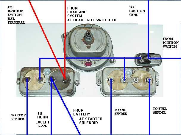
Gauge Wiring Diagram drawn from
actual 1951 Wagon, 4x4, F4 wiring harness.
Instrument Voltage Regulator - Screwed to the Fuel/Oil gauge housing. View backside of instrument panel
Temperature Sending Unit - L6, left rear of cylinder head - F4, right rear of cylinder head
Oil Pressure Sending Unit - L6, Right rear of engine block - F4, Left rear of engine block
Fuel Tank Sending Unit - Inside the fuel tank screwed to the top
flange
12 volt Conversion Information
The Fuel, Oil and Temperature gauges will operate normally on 12 volts. The higher voltage can shorten the life of the Instrument Voltage Regulator. The voltage can be reduced several ways. Probably the simplest method is to use a resistor in series with the power lead of the Instrument Voltage Regulator. A current limiting15-ohm power resistor reduces the voltage to about 6 volts. Another method is to use a voltage regulator. Converters are available from electronic stores that are used to power small electronic devices from the cigarette lighter of a car. Usually they come with plug adapters to fit the power plug of small radios and tape players. Select a converter that has a 6-volt output. Cut the cigarette plug off the converter. Remove the power feed wire from the instrument voltage regulator. Connect the converter wire that was hooked to the center contact of the cigarette plug to the removed power feed wire from the instrument voltage regulator. Connect the other wire that went to the cigarette plug to ground. Connect the 6-volt converter output to the ignition terminal of the Instrument Voltage Regulator. Be sure the wires are connected with the correct polarity.
The amp gauge measures current and is not affected by voltage.
E-mail me the solution to your gauge problem and when I see a common
problem I will add it to the list. Click
here for contact information.
Various problems
The most common problems with the gauges are bad connections and modified wiring. On older vehicles the connections and wires have corroded to the point where the resistance is too high. Previous wire harness repairs may have changed the wiring, rendering gauges inoperative. Check all wires for proper routing. Check all connections and grounds with an ohmmeter. Use a jumper wire to connect the case of the Instrument Voltage Regulator to the battery ground post to help isolate poor ground connections.
Fuel gauge doesn't go all the way to full
1. The fuel tank doesn't have a good ground. Run a wire from a sending unit mounting screw to a clean connection on the frame.
2. Float needs adjustment. The float hits the inside top of the fuel tank before the sending unit resistance is less than 10 ohms. Bend the float lever and check with an ohmmeter.
Fuel, Temperature and Oil Gauges all read too high
1. The Instrument Voltage regulator has a bad ground. Clean and tighten the mount screw of the regulator and clean the mounting surfaces of the Fuel/Oil gauge housing.