Home | Site Map | Contact Information
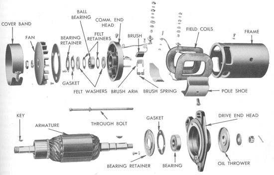
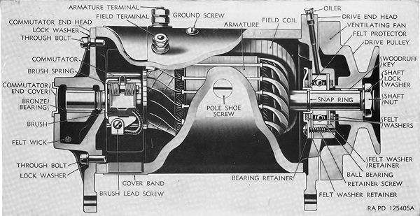
CJ-3A Generators

CJ-3A Generators
Willys-Overland and Electric Auto-Lite had a very close relationship so the majority of Willys electrical components were made by Auto-Lite. Original CJ-3A generators were the two brush, Type A, variety. There were 3 different generators used on CJ-3As. The GDZ-4817A was used up to mid 1950. Then came the GDZ-6001D up to the beginning of the 1953 model year when the GGW-4801D entered production. See the Dating a CJ-3A article for more information.

How does a generator work?
A generator operates just opposite of an electric motor. It converts motion into electricity. Electricity is generated when an electrical conductor is moved through a magnetic field. The amount of electricity is determined by the strength of the magnetic field and the speed, size, and number of conductors moving through the field. The size and number of conductors is fixed by the design of the generator and the speed is determined by engine conditions. The strength of the field can be varied by changing the amount of current flowing through the field coils. The field coil current, and thus the generator output, is controlled by a voltage regulator.


When the generator armature revolves, its conductors cut through the magnetic field supplied by the field coils. This generates electricity in each of the armature conductors. As each conductor in the revolving armature passes first a north magnetic pole then a south magnetic pole, current is produced first in one direction then the other. The commutator and brushes act as a switch which changes the connections at the proper instant to deliver direct current at the armature terminal (sometimes called the generator terminal). The field excitation current is self-supplied by the generator. When the generator is stopped, there is no field current but there is a slight residual magnetism in the pole shoes. The residual magnetism is sufficient to start the generating process which in turn increases the field coil strength and therefore the generated electricity. This building up of the generator output continues until it reaches about 7.5 volts where the regulating action begins to control the field current. If the residual magnetism of the pole shoes is lost the generator must be polarized. The magnetism can be lost by long periods of inactivity or improper electrical connections.

Identifying the generator and components

An Auto-lite generator will have a tag with the generator number stamped on it, hopefully the tag is still in place. The terminals are labeled in the illustration. The armature terminal (also referred to as the generator terminal) is a larger diameter than the field terminal since more current flows in that circuit. The ground screw is simply threaded into the generator frame.

The voltage regulator must be matched to the generator, see chart below for the proper regulator number.

CJ-3As used Type A generators, other Willys Jeeps did use Type B. If the Type is unknown skip down to Determining the Generator Type.

On Vehicle Testing

First make a visual check of the wiring and battery cables. Repair any frayed wires and loose or dirty connections. Check the drive belt tension per the service manual. If everything looks good the following tests will require a high quality digital volt meter or an older analog meter. Inexpensive digital meters can give unexpected results in these circuits. Skipping any test can lead to misdiagnosis.
Continue here for low charge testing
Continue here for high charge testing

Determining the generator Type


It is important to know if the generator is a Type A or Type B for service and repair. The electrical difference is the internal connection of the field coils. On Type A the internal field connection is to the armature (+) and on Type B the field is connected to ground (-) internally. If the armature is electrically removed from the circuit a simple continuity check can be made to determine if the field is connected to ground or the armature terminal.
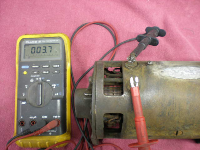
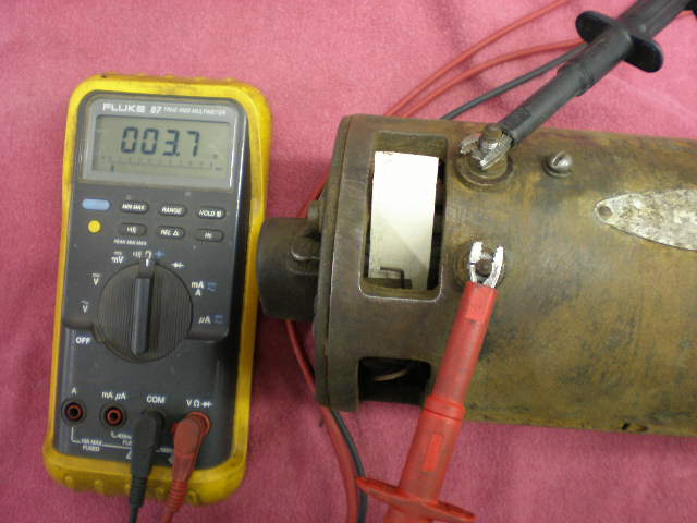
First set the multi-meter to the low ohms range. Connect one lead to the field terminal (small diameter) and then measure the resistance to the armature terminal (large diameter) with the other lead. See the photo to the right. A normal reading is less than 10 ohms, here it is 3.7 ohms.

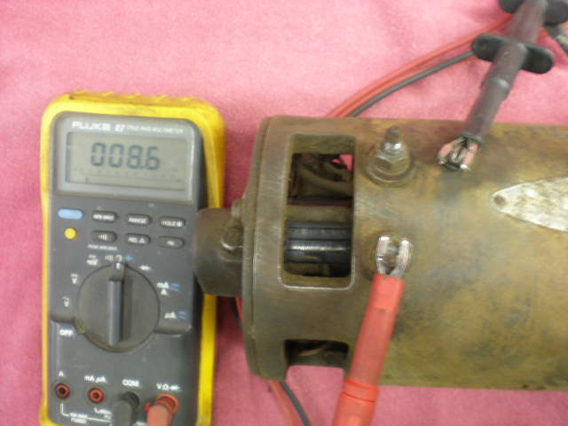
Now move the lead from the Armature terminal to the Ground screw. Again the normal reading of less than 10 ohms is seen in the photo. If the resistance of these two checks is not less than 10 ohms each there is an internal problem with the generator that must be repaired first.


To isolate the armature for this test remove the brush cover band. Lift one of the brushes and slip a cardboard strip between the brush and the commutator. It does not matter which brush is insulated since either will break the armature circuit continuity. In the photo the generator housing, or frame, has been removed for clarity. The cardboard strip can be inserted through the brush access holes without generator disassembly.

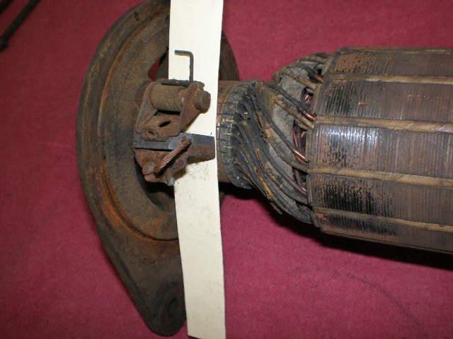
With the armature out of the circuit repeat the first two tests. Check the resistance from the field terminal to the armature terminal. For a Type A generator this measurement will remain unchanged (less than 10 ohms) as seen in the photo. This is because internally the field is connected to the armature terminal. If this was a Type B generator the reading would be an open circuit, or no continuity.

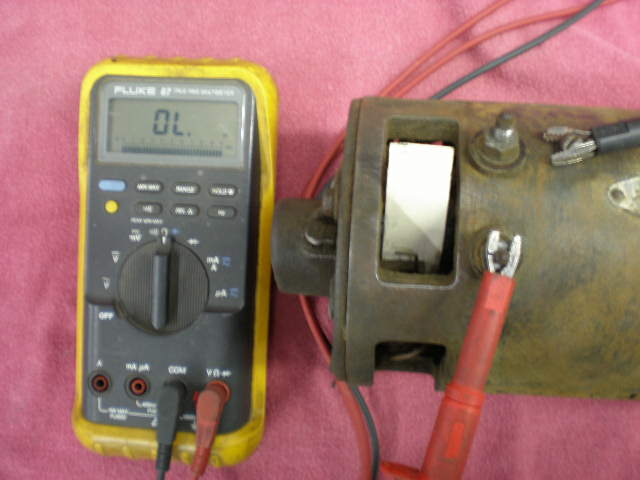
Now move the test lead to the ground screw. For a Type A generator this is now an open circuit, or no continuity, as seen on the multi-meter. If this was a Type B generator this reading would be less than 10 ohms because internally the field is connected to ground.


Polarizing a generator

The residual magnetism remaining in the field pole shoes is what enables the generator to start charging. After a long period of inactivity, or during replacement or testing of the generator the residual magnetism may be lost, or the polarity could accidentally
get reversed. A generator should be polarized after it is installed and connected, but before the engine is started. For Type A, as used on a CJ-3A, momentarily connect a jumper wire from the battery to the armature (generator) terminals of the voltage regulator. Just a touch of the jumper is all that is required. If you have a Type B, disconnect the field wire from the regulator and momentarily touch this wire to the battery terminal.

CJ-3A Auto-lite Generator Component Part numbers and Specifications

Generator Number


GDZ-48l7A GDZ-600lD GGW-4801D
Armature GDZ-2006F GGY-2006F GGW-2006F
Brush Set GGU-2012S GGY-2012S GGY-2012BS
Commutator End Head Assembly
GDZ-2087A GGW-2002S GGW-2002S
Commutator End Bearing GBF-79 GGU-38A GGU-38A
Brush Arm (2 used)
GCJ-26 GCJ-26 GCJ-26
Brush Spring (2 used) GBW-45 GGY-45 GGY-45
Field Coil Assembly
GDZ-1005 GGW-1005 GGW-1005
Drive End Head Assy. GDZ-1088A GGW-1003 GGW-1003
Drive End Bearing
X-295 X-295 X-295
Pulley or Fan SP-1885 SP-1986 SP-1986
Voltage Regulator VRP-6003A VRP-6003A VBE-6105A
Generator Specifications


Rated Volts
6V 6V 6V
Rotation at the drive end
Clockwise Clockwise Clockwise
Brush Spring Tension
35-53oz. 35-53oz. 35-53oz.
Field Coil Draw
5.0V, 1.3-1.5A 5.0V, 1.3-1.5A 5.0V, 1.4-1.5A
Motoring Draw
5.0V, 3.9-4.4A 5.0V, 3.9-4.4A 5.0V, 4.1-4.6A
Output
8.0V,  35.0A max,  2000 rpm max 8.0V,  35.0A max,  2000 rpm max 8.0V,  45.0A max,  2125 rpm max

Thanks to Karl Russel for the simple generator type identification test.
Part numbers from the 1955 Auto-lite Service Parts Catalog
Generator Specifications from 1952 Auto-lite Electrical Equipment Specification Book
Generator description of operation from TM 9-1825B Electrical Equipment (Auto-lite)

The CJ-3A Story | CJ-3A Photos | CJ-3A Specs and Tech Tips | CJ-3A Literature | Siblings of the CJ-3A | Accessories | Links


  3/07 www.cj3a.info © 2007